Quick Guide: Anaerobic Fermentation with CellMaker
Introduction
Anaerobes are bacteria that cannot grow in environments where oxygen is present, as oxygen is toxic to them. These microorganisms are commonly found in oxygen-free habitats and are a major component of the human microflora, particularly in mucosal sites throughout the body. Naturally occurring anaerobes, while typically harmless in their usual environments, can become pathogenic when displaced from their natural habitat. Anaerobic infections are a common cause of illness, with some cases being severe or even life-threatening. Additionally, certain species like Clostridium, primarily found in soil, can also cause infections in humans.
The mechanisms through which anaerobes cause infections remain largely unclear and require further research. An exception is Clostridia, which has been extensively studied and is known for causing diseases such as tetanus, pseudomembranous colitis, and food poisoning from contaminated meat and poultry (Hentges, 1996).
Beyond their pathogenic characteristics, anaerobic bacteria have a wide range of industrial applications. They are used in the production of biofuels, dairy products, fermented foods, brewing processes, and enzymes. Their genomes encode proteins that facilitate the production of valuable by-products with various industrial uses, making them highly versatile in commercial applications (Patidar and Prakash, 2022). One of the key advantages of anaerobic processes is their lower energy requirements. Compared to aerobic cultures, anaerobes grow more slowly, leading to reduced biomass production. This slower growth allows for a higher proportion of carbon to be converted into the desired end product, resulting in increased yields (Hiang & Tang, 2007).
However, maintaining strict anaerobic conditions is a significant challenge. Even trace amounts of oxygen can compromise culture viability, leading to inconsistent results and potentially failed batches (Justesen & Justesen, 2013). This is where bioreactors offer a crucial advantage, providing precise control over bioprocess parameters to ensure consistent, oxygen-free conditions (Saeed et al., 2023).
This application note outlines the setup, process, and outcomes of anaerobic bacterial fermentation trials in the CellMaker Plus bioreactor system, demonstrating it’s reliability and efficiency for both scientific research and industrial applications.
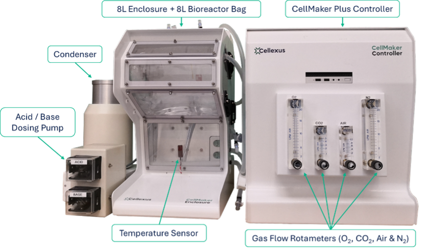
System Overview
With ports to accept auxiliary gas lines in addition to the integral compressed air supply, CellMaker can supply the culture with the perfect blend of gasses, whether working under aerobic and anaerobic conditions.
Bioreactor Assembly
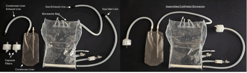
To preserve sterility of the bioreactor, remove the four components parts from the sterile packaging within a laminar flow hood or anaerobic chamber using good aseptic technique. Within the flow hood/chamber connect the bioreactor bag gas exhaust line to the inlet of the Condenser Liner. Next, fit the capsule filters to the Condenser Liner exhaust line and the Gas Inlet Line to create a closed system.
At this point install any immersion probes that are being used and the media fill/harvest tubing.
Once assembled the bioreactor can be removed from the flow hood/chamber and fitted into the CellMaker Enclosure. Alternatively, the 8L Enclosure can often be installed within an anaerobic chamber with the Controller remaining outside and cabling routed through cabinet cable port.
Once the bioreactor has been installed in the Enclosure it can be filled with desired volume of media and heated to the required temperature.
Gas Connections
Gasses are supplied to the CellMaker Controller via standard 8 mm push-fit nylon gas lines from any supply source which has been regulated to a 2.5-5 bar pressure.
| Integrated compressor | Gas Inputs | ||||
| Aux | 2 | 3 | |||
| CellMaker Regular | Typical Gas | Atmospheric air | O2 | N/A | N/A |
| Control | Software Set-point (lpm) | Software Set-point (lpm) | N/A | N/A | |
| CellMaker Plus | Typical Gas | Atmospheric air | O2 | N2 | CO2 |
| Control | Software Set-point (lpm) | Software Set-point (lpm) & Automatic (DO%) | Manual Set-point (lpm) | Manual Set-point (lpm) |
|
NB: Whilst the above indicates the typical gasses used for the Gas Inputs these can be interchanged and exchanged as required by the protocol being run. CellMaker is compatible with any non-corrosive gasses.
Air is supplied via an integrated compressor within the CellMaker Controller unit.
The gasses are blended within the CellMaker controller and supplied to the CellMaker Bioreactor Gas Inlet Line via a 0.22 µm capsule filter to maintain sterility of the culture.
The Bioreactor’s exhaust gas passes through a cooled condenser unit to remove moisture and ultimately through a 0.22 µm capsule filter before venting to the environment, into a fume cabinet or extractor system . In the case of anaerobic experiments which are venting into an environment containing normal atmosphere it is recommended that a one-way valve be incorporated within the exhaust line to preventing atmospheric air from re-entering the system.
Anaerobic Cell Culture
Step 1 – Connect gasses
CellMaker Regular – replace O2 supply line with anaerobic gas / pre-blended gas mixture as required.
CellMaker Plus – replace O2 supply line with anaerobic gas / gas mixture as required. If using a non-standard or variable anaerobic gas mix which requires blending, use the “O2/Aux” line to control the minor component gas/gasses with gas input 2/3 (“N2” & “CO2” rotameters) for the bulk gas flow. If using the CellMaker Plus system’s DO probe to monitor the process then we recommend calibrating the probe before use – see user manual for details.
Step 2 – Turn off air supply
Close the system’s air inlet entirely to prevent atmospheric oxygen from entering the bioreactor through the air pump, this is achieved by:
- fully closing the “Air” rotameter
- set the “Air Flow (lpm) SP’ value in the CellMaker software to zero
Step 3 – Begin anaerobic gas flow
CellMaker Regular – Fully open the “O2/Aux” rotameter and set the “O2 Flow (lpm) SP” value in the CellMaker software to the desired volumetric gas flow rate.
CellMaker Plus – Fully open the “O2/Aux” rotameter and any additional gas inputs being used and set the “O2 Flow (lpm) SP” value in the CellMaker software to the desired volumetric gas flow rate.
To begin the gas flow simply hit the ‘Run’ button in the CellMaker software. Where gas is being supplied to the bioreactor via gas inputs 2/3 (“N2” & “CO2” rotameters) these can now be adjusted to provide the desired volumetric flow rates.
Step 4 – Culture
Prior to inoculation with the chosen bacterium a 20-30 minute period of sparging is typically employed to remove any inherent oxygen within the system. The CellMaker’s recipe mode function can be employed to automate sparging flow rates via the “O2/Aux” line, intervals of sparging as well as enable batch feeding and anti-foam addition. The precise timing, duration, and flow rate should be optimised by the end-user to suit their particular application. The mass flow controller (MFC) on the “O2/Aux” line offers flexible control and is capable of regulating gas flow rates from 0.3 lpm to 10 lpm, allowing for tailored adjustments according to process needs.
Note: The CellMaker Plus system’s dissolved oxygen (DO) sensor can be calibrated prior to sparging with anaerobic gas and used to monitor and maintain anaerobic conditions throughout the culture process.
Summary
The CellMaker bioreactors are an effective and adaptable solution for anaerobic fermentation. Their ability to maintain a strictly oxygen-free environment, combined with its flexibility to accommodate a variety of non-corrosive gases, makes them suitable for a wide range of applications. Whether used in research aimed at understanding anaerobic mechanisms or for scaling up the production of valuable by-products, the system ensures precise control of bioprocess parameters, supporting both scientific discovery and industrial productivity.
References
Hentges, D.J. (1996) ‘Chapter 17 Anaerobes: General Characteristics’, in Medical Microbiology. 4th edn. Galveston, Texas: University of Texas Medical Branch at Galveston.
Huang, W.-C. and Tang, I.-C. (2007) ‘Bacterial and yeast cultures – process characteristics, products, and applications’, Bioprocessing for Value-Added Products from Renewable Resources, pp. 185–223. doi:10.1016/b978-044452114-9/50009-8.
Justesen, T. and Justesen, U.S. (2013) ‘A simple and sensitive quality control method of the anaerobic atmosphere for identification and antimicrobial susceptibility testing of anaerobic bacteria’, Diagnostic Microbiology and Infectious Disease, 76(2), pp. 138–140. doi:10.1016/j.diagmicrobio.2013.02.014.
Patidar, P. and Prakash, T. (2022) ‘Decoding the roles of extremophilic microbes in the anaerobic environments: Past, present, and future’, Current Research in Microbial Sciences, 3, p. 100146. doi:10.1016/j.crmicr.2022.100146.
Saeed, M.U. et al. (2023) ‘Microbial Remediation for Environmental Cleanup’, Advanced Microbial Technology for Sustainable Agriculture and Environment, pp. 247–274. doi:10.1016/b978-0-323-95090-9.00010-8.